SOLAR FAN
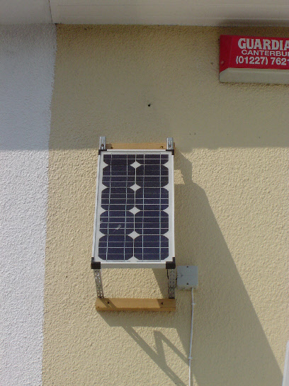
The panel is rated at 20W, nominal output voltage 12V. From measurements, the actual
open circuit voltage will vary from 15V to 20V on a clear sunny day. On a clear
summers day at mid-
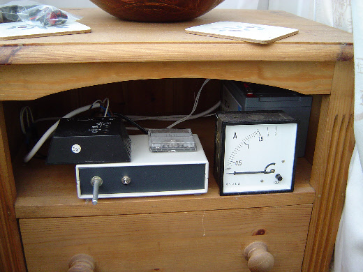
The battery is a 12V, 12AH Lead Acid Gel battery. At full speed, the fan draws a current of 0.7A. It can be seen from Table 1 that between the hours of 09:00 and 18:00 there should be an excess of power. During this time the battery will charge up, the maximum charge being regulated by the charge controller. When the battery voltage reaches approximately 14.0V the charge controller will stop charging the battery. Outside these times power will be drawn from the battery, so it will start to discharge. If the battery voltage drops too low (Below 10.8V), the fan will be switched off by the charge controller. When fully charged, the battery should be able to operate the fan for 8.5hours before it reaches 50% of it’s charge.
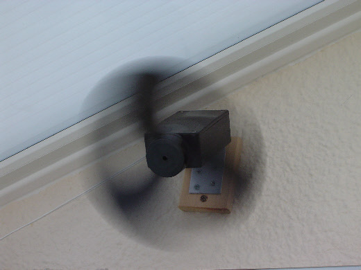
A 12v(nominal) DC motor is being used with 8” fan blades, the speed of which is controlled using a PWM (Pulse Width Modulation Circuit).
Once up to speed, the motor draws a current of 700mA at 12V, this rises to 900mA at 14V.
The 12AH battery should be charged at approx no more than 20% of its rated Current which is 2.4A. With the motor switched off, the maximum current available from the solar panel is 1.7A. As the battery charges, the current will gradually decrease and the voltage increase. When the motor is operating, the maximum current available for charging the battery will be reduced to 1.7A – 0.7A = 1A.
The above figures are ideal values (Always Sunny) . In practice, it will be interesting to see how well the system performs throughout the summer. I plan to take various measurements during the summer. When these are available, i'll include them on this page.
Solar Fan Project
I started this project because I wanted to experiment with solar power. I have a south facing conservatory which, in the summer has the sun on it almost all day and can get very hot. I wanted to have a means of keeping the air flowing around it, without having a fan connected to the mains power all day. After researching on the Internet this is the system I have constructed
Diagram 1. Equipment Diagram
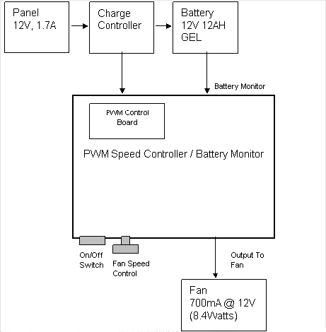
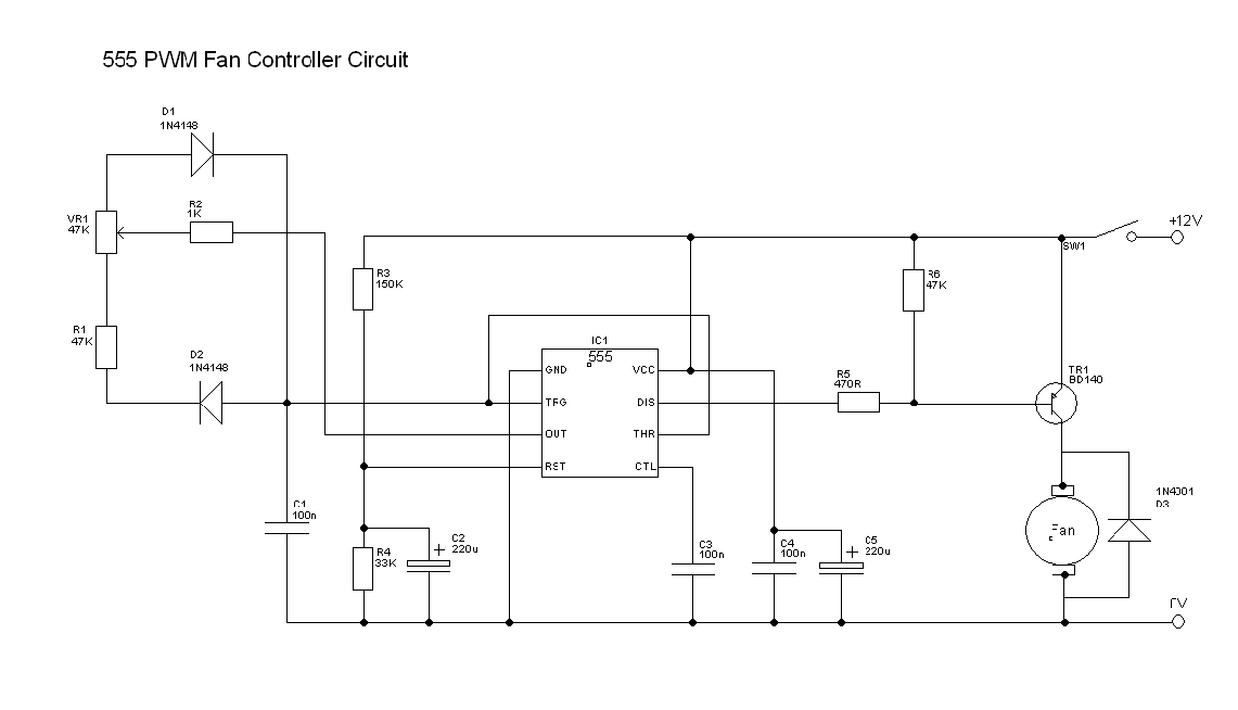
Diagram 2. PWM Fan Speed Controller Circuit
This circuit was copied from www.nomad.ee/micros/pwm555.html
Some excellent information on Pulse Width Modulation can be found on this sites.
This circuit will provide almost 0 to 100% pulse width regulation using VR1, while keeping the oscillator frequency relatively stable. The frequency is dependent on values of VR1 and C1, values shown will give a frequency range from about 170 to 200 Hz. Any 555 chip will do, CMOS is fine as well. Diodes are not critical, I used 1N4148.
R2, R3 and C3 form a kick-
The Out pin of the 555 is used to drive the PWM cycle, so the discharge pin is used
to drive the output transistor instead. This is open collector output, and is used
as active low signal, so that the kick-
R1 in series with VR1 gives a minimum voltage that will still run the fan. R2 limits the current when VR1 is at the zero resistance end of travel.
Waveforms
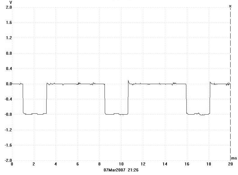
Fan at slowest speed
When the base emitter voltage is low the transistor will conduct.
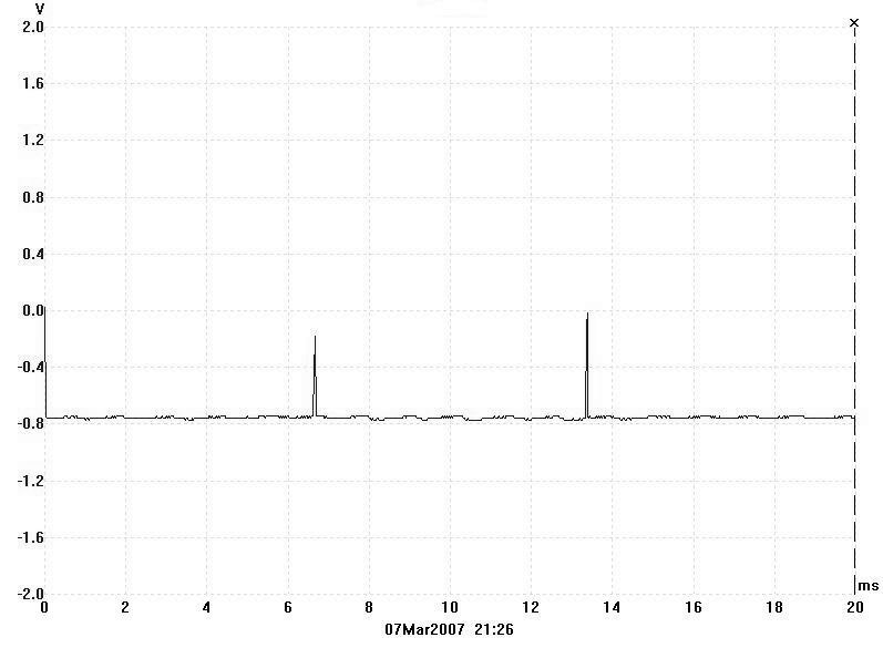
Fan at Fastest speed
When the base emitter voltage is low the transistor will conduct.
Install Pictures

Download full design document (pdf)