Cosmic Night Light
This project describes how to make a night light using colour change LED’s encased in resin.
What’s needed
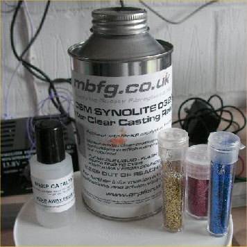
Resin
Catalyst
Glitter
Resin Dye -
Mould
Small Polystyrene
sheet
Colour change LED’s
Resistor
Soldering Iron
Resistor (4.7 ohms)
5v power supply
(from old mobile phone)
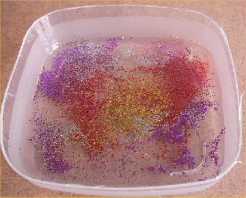
First I mixed up the resin in a plastic pot and added approximately 2% mixture of the catalyst.
The amount of resin used will depend on the size of the mould. You need to aim for a resin layer of about 5mm.
I then sprinkled the glitter on to the top of the resin.
The resin now takes 24 hours to set.
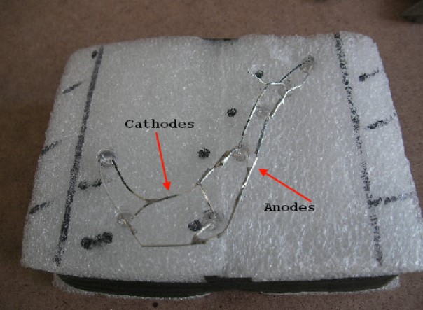
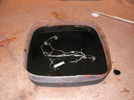
While the resin was setting I took my piece of polystyrene and marked out the positions of the LED’s in reverse to the design I wanted in the night light. I then mounted the LED’s in the polystyrene by making holes using a pencil. The LED’s were mounted in the holes.
The LED’s were then connected in Parallel, by soldering all the Anodes together and then all the Cathodes together.
At this point I checked the LED’s by applying 4V across the Anode and Cathode.
The next stage (not shown here) was to mix up enough resin for another layer of about 5mm thick. This was poured into the mould.
Small drops of dye were dripped on to the top of the resin and using a toothpick a pretty pattern made. Only use small amounts of dye, so as not to obscure too much light from the LED’s.
Once the resin had set, I mixed up some more resin (5mm layer) and poured it into the mould. This covered the layer with the dye. I then laid the LED’s face down in the dye.
I then had to wait another 24 hours for the resin to set.
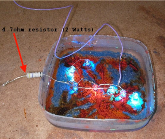
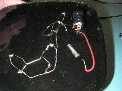
After the resin set, I soldered a 4.7ohm (2 Watt) resistor to the joined Anodes of the LED’s.
This resistor will limit the voltage across the LED’s to about 4 Volts, enabling the circuit to be operated from a 5 Volt supply.
The next stage was to mix up some more resin, enough for a layer of about 2-
To the resin, I added some black dye. I then poured this into the mould so that it completely covered the LED’s, making sure that at least a part of the the Anode and the Cathode wires were not covered by resin.
This was to allow wires to be soldered to them.
I soldered a Red wire to the Anode and a Black wire to the Cathode.
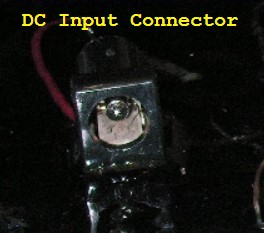
I then connected the two wires to the DC input connector.
The type of connector used will depend on the power supply. In my case, I’m using an old mobile phone supply.
Finally I mixed up a clear layer of resin to cover all the bare wires. And the base of the DC input connector.
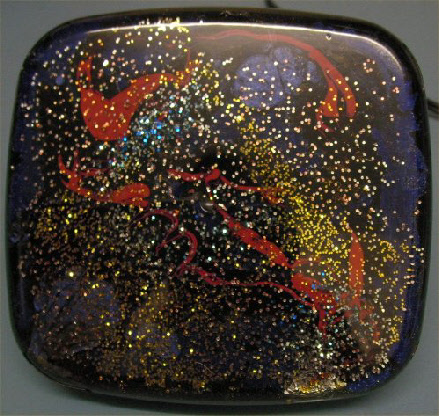
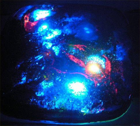
When the final layer of resin was set, I removed the light from the mould applied the power, and this is what I ended up with.