BATTERY ANALYSER

Download information pack, including circuit diagrams and software.
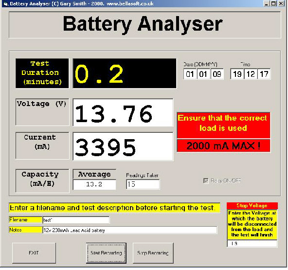
This project is to enable the discharge curves and Capacity of various batteries to be measured.
A battery under test is discharged through a load, which will vary depending on the type of battery being analysed. The voltage of the battery and current delivered through the load are monitored by a computer until the battery voltage falls to the minimum discharge level. The software will then display the capacity of the battery. The unit is controlled via the Parallel port of a PC using Visual Basic 6.
The main components of the circuit are:
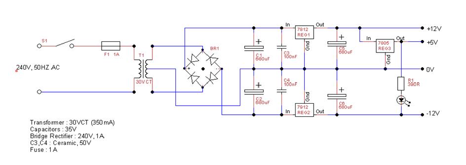
Power Supply
This converts the 240V AC mains input to +12V, -
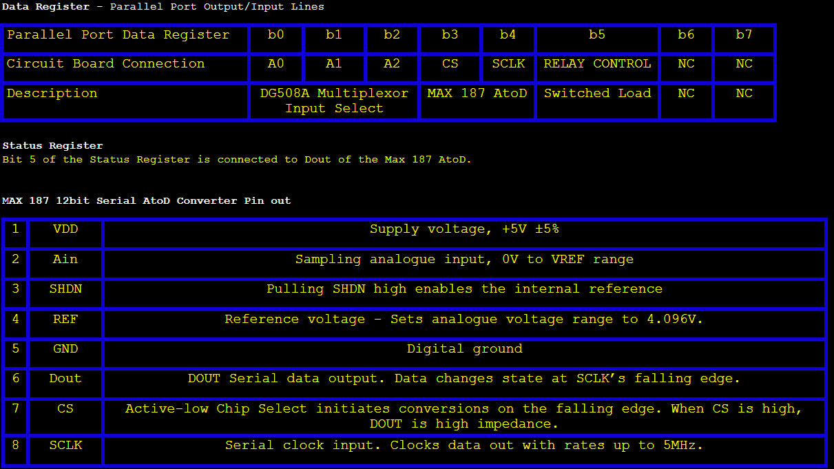
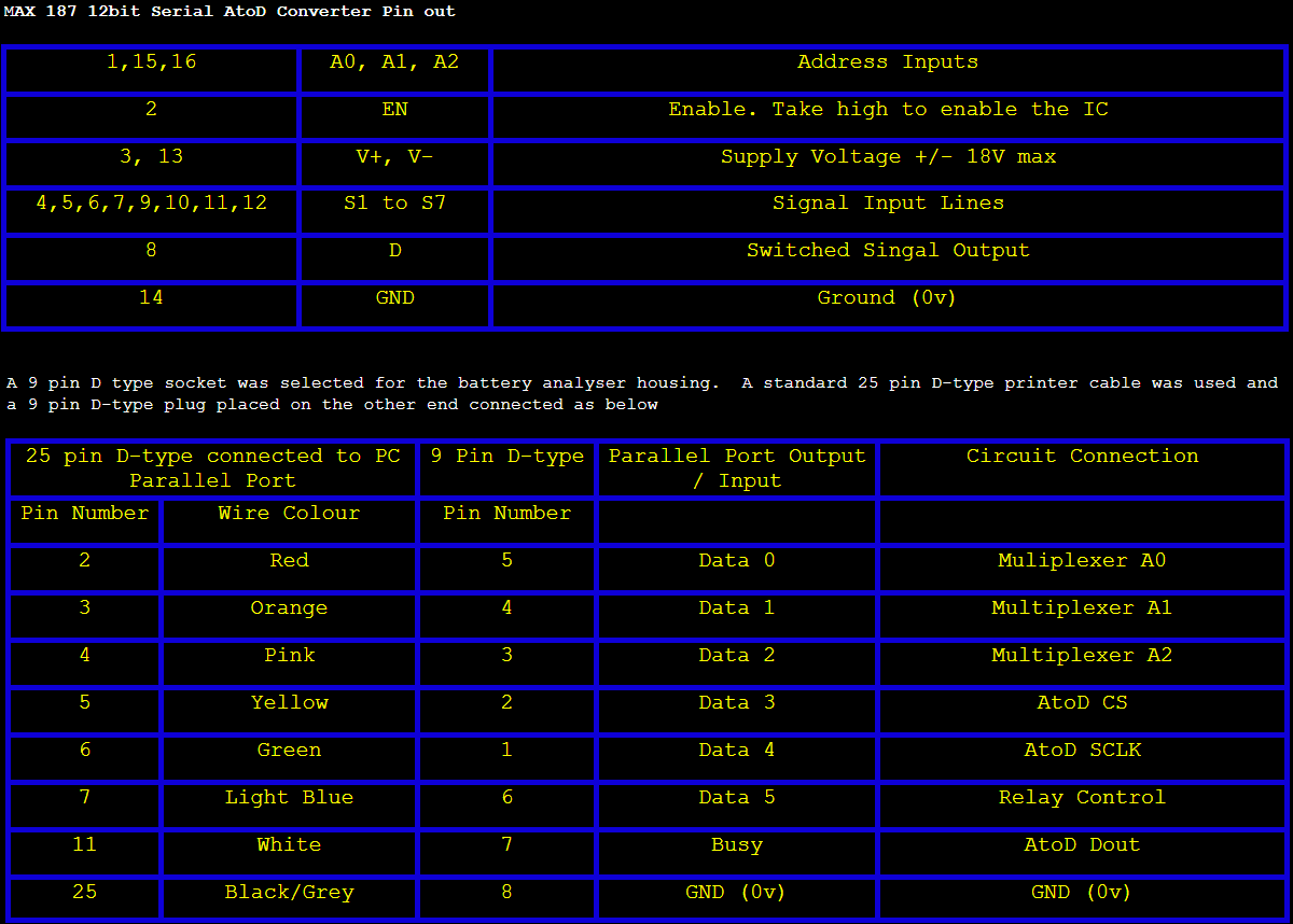
MAX187 12bit Serial A to D Converter and MAX DG508A Multiplexer
Takes inputs from
the Voltage Amplifier (Load Current) and Voltage Reducer (Battery Voltage) circuit
via the Multiplexer.
Relay Control Circuit
Switches the Load on or off using a 12V relay.
Voltage Amplifier
Amplifies the Shunt voltage measured across a 0.1ohm resistor in
series with the load to bring it within the range of the A to D converter
Voltage Reducer Circuit
Reduces the battery voltage to bring it within the range of
the A to D converter
Load
A range of loads will be used depending on the battery type under test.
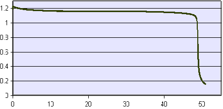
Measured discharge characteristic of a 1.2v, 800mAh AA NiCd battery.
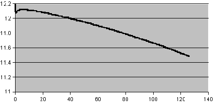
Measured discharge characteristic of a 12v, 7Ah Lead Acid battery.
Three Voltage Power Supply
This circuit provides a +/-
+12V: Relay Coil
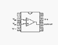
Voltage Amplifier (741 op-
Multiplexer (MAX DG508A)
-
Multiplexer (MAX DG508A)
+5V: AtoD converter (MAX187)
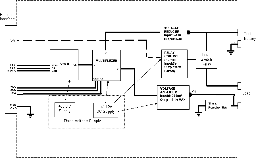
Basic Circuit Block Diagram
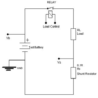
Load Control Circuit
This circuit consists of the following:
Test Battery
For the circuit shown below, this would typically be any Lead Acid battery with a rating of >1Ah. With different loads, it will be possible to test other batteries.
Load (RL).
This is provided by a load box providing a number of different loads depending on the battery being tested.
Shunt Resistor (Rs)
This enables the circuit current to be measured. This is a Bare Element Resistor, chosen for its excellent Temperature Coefficient. The circuit current is equal to : I = Vs / Rs. In practice I will measure the circuit current using a DMM at different levels and convert the measured voltage into a current reading using software.
Relay
The switching of this relay will be computer controlled; therefore the computer can remove the load when the battery voltage drops below a certain value.
Vb= Battery Voltage.
Vs = Shunt Voltage (Proportional to Circuit Current)
The Load is controlled via the Relay.
EG. 12v, Test Battery
6R Load
Nominal Circuit Current I = Vb/(RL+Rs)
I= 12/6.1 = 2A (24W)
The voltage developed across Rs should be : V = I * R
V = 2 * 0.1 = 0.2V (200mV)
The computer closes the relay to start the discharge cycle. In practise we won’t allow the battery to discharge below a certain value.
Voltage Amplifier
The voltage measured across the shunt resistor will vary from approximately 0v to
200mV depending on the load used. The MAX187 AtoD has an input voltage range of
0 to 4v. The non-
Relay Control Circuit (Load Control)
The relay is triggered by the output of b5 on the parallel port. The relay coil requires 12v to energise. The resistance of the coil is 200ohms, therefore a current of 12v / 200ohms = 60mA will be drawn. The parallel port output of 5v at a maximum of 12mA isn’t sufficient to energise the relay coil. The circuit below will allow the +5v signal from the parallel port to switch +12v.
The diode protects the transistor from back EMF which will be generated when the relay coil is switched off.
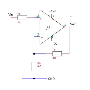
Calculation of Gain
Gain = (Rf+Rin)/Rin
Gain = (47000+4700)/4700 = 11
The amplifier was constructed on breadboard and tested as follow:
Input Voltage Output Voltage Gain
50.0mV 0.568V 11.4
123mV 1.362V 11.0
So, in practise thIS 741 gives a gain of approximately 11.
Voltage Reducer Circuit
The AtoD converter can only accept voltage inputs of up to +4v. As the max voltage of a battery could be >13.5V the voltage needs to be scaled down. A simple potential divider can be used to achieve this.
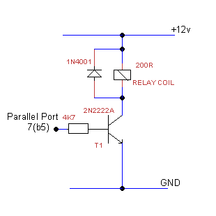
Relay Coil Load Current (Ic) = 12v/200R = 60mA
Load Current / Max parallel port current
= 60 / 12 = 5.
We need a transistor with an hfe >5. It’s good practise to choose a transistor hfe of 5x this value i.e 25.
2N2222A chosen – hfe=100, IC(max)=800mA
Calculate value for base resistor:
Rb = (Vc . hfe) / (5 . Ic)
Rb = (12 . 100) / (5 . 0.060) = 4000
Rb = 4k7 chosen.
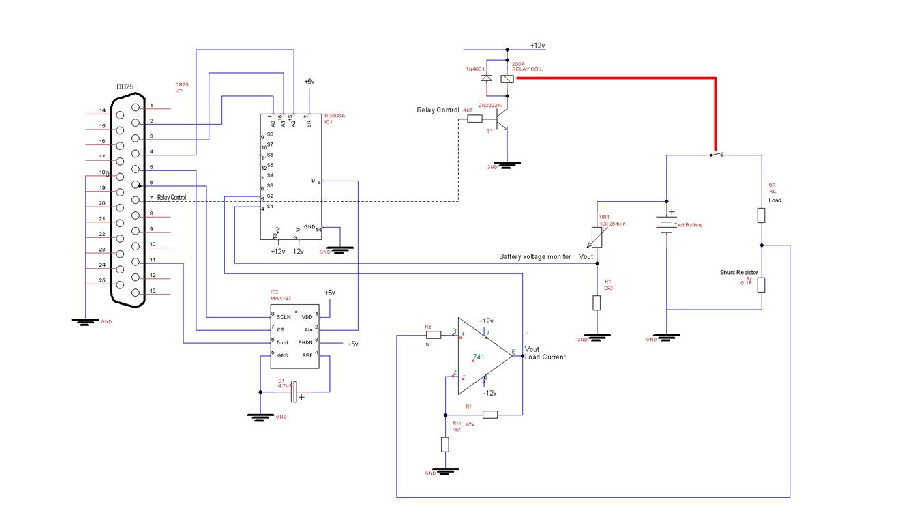
Complete Circuit Diagram, excluding PSU.
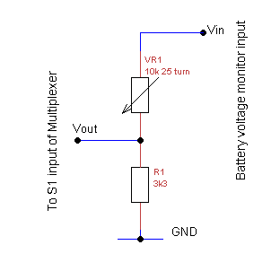
Vout = (R1 / (R1 + VR1)) . Vin.
Vin is measured from the positive terminal of the battery under test.
A test voltage of 13.5V was inputted and VR1 adjusted to give make Vout 4v.
The Battery Voltage from the Voltage Reducer circuit and the Load Current from the Voltage Amplifier are connected to the S1 & S2 inputs of the multiplexor respectively. Address lines A0 to A3 on the multiplexor are used to select the desired input (S1 or S2). The multiplexor can take up to 8 inputs, but for this project I am only using two.
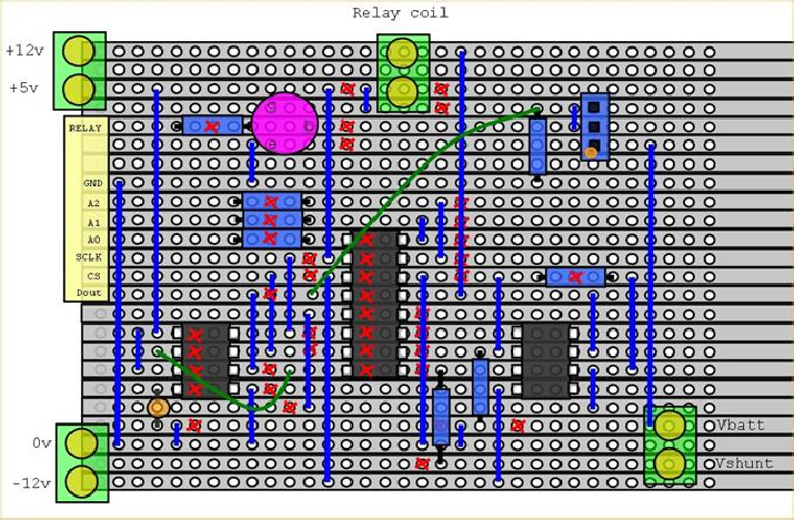
Stripboard Layout
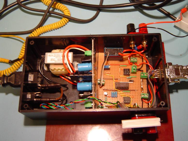
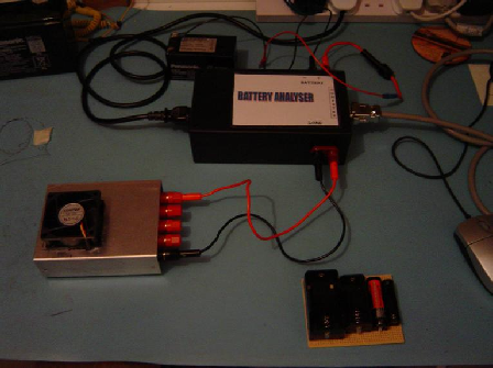
Constructed unit showing PSU board and interface board mounted in box
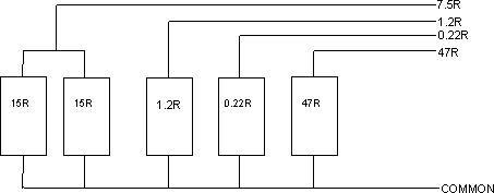
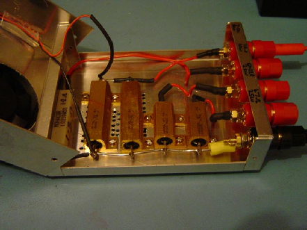
Test Load Box
The test loads are housed within an aluminium casing. Each load is brought outside the box using banana terminals. The test box contains the following loads:
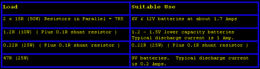
Note. If used as above, heat dissipation won’t be a problem. Only the two 15R resistors in parallel will get hot. With a fully charged 12V battery, the maximum temperature of the resistors was measured to be 60°C. By placing a 12V fan across the two resistors, and drilling ventilation holes around the resistors, the temperature dropped to less than 50°C. The resistors are rated at 200°C.
Calibration
The analyser was powered up with a 12v, 20W lamp as a load and a 12V, 1300mAh Lead Acid battery.
Voltage Calibration
The analyser was set to measure battery voltage and the output of the AtoD converter recorded. The AtoD converter output will be a value between 0 and 4096 (12 bit AtoD). To calibrate the output, we need to measure the actual battery voltage using a DMM.
AtoD Output Actual Battery Voltage
3620 12.17V
If we now divide the AtoD Output by the battery voltage we get a calibration factor of : 3620 / 12.17 = 297.5
For the software to display the actual battery voltage all it needs to do is divide the AtoD output by the calibration factor.
Current Calibration
The analyser was set to measure current and as above, the AtoD converter output recorded. The actual current was measured using a DMM in series with the battery and load.
AtoD Output Actual Battery Current
1860 1546mA
If we now divide the AtoD Output by the current we get a calibration factor of : 1860 / 1546 = 1.203
For the software to display the actual current all it needs to do is divide the AtoD output by the calibration factor.
Measurement of Cal Factor at lower level of Load current
A 1.2V, 2600mAh NiMi battery was used with the 12V, 20W lamp.
<<<Voltage>>>
AtoD Output Actual Battery Voltage Cal Factor
327 1.140 286.8
<<<Current>>>
AtoD Output Actual Battery Current Cal Factor
636 523mA 1.216
Analyser Linearity
Now that the Cal Factor has been calculated at two different levels, we can work out the linearity of the analyser. At 12V the cal factor is 297.5. At 1.2V the cal factor is 286.8. The percentage difference between the two cal factors is: 3.6%. So, the analyser can measure the battery voltage with a linearity of at least 3.6% between 1.2V and 12V
Likewise, for Current:
Cal factor at 523mA = 1.216
Cal Factor at1546mA = 1.203
Linearity between 523mA and 1546mA = 0.25%
NOTE: This circuit is only suitable for analysing batteries up to a maximum of 14V.
By up-
Basic Circuit Diagram of Load Box
Interfacing with the Parallel Port
The Data Register and the Status Register of the parallel port are used to interface with the analyser. This can be implemented fairly easily using Visual Basic 6 or MS QuickBasic.